
|
|||
 |
|
||||||||
General-purpose Relays
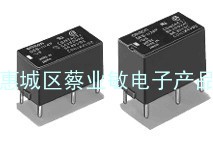
Models for DC Loads
Standard Models
MKS1XT-10, MKS2XT-11
Models with Built-in Operation Indicators
MKS1XTN-10, MKS2XTN-11
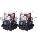
Models for AC Loads
Standard Models
MKS1T-10, MKS2T-11
Models with Built-in Operation Indicators
MKS1TN-10, MKS2TN-11
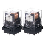
Models for DC Loads
Models with Test Button
MKS1XTI-10, MKS2XTI-11
Models with Test Button and Built-in Operation Indicators
MKS1XTIN-10, MKS2XTIN-11
Models for AC Loads
Models with Test Button
MKS1TI-10, MKS2TI-11
Models with Test Button and Built-in Operation Indicators
MKS1TIN-10, MKS2TIN-11
Connecting Socket
Back-connecting Socket
P7M-06P
Front-connecting Socket
P7MF-06
P7MF-06-D
Note:
1.The internal connecti*** diagram is for the MKS2(X)T[][]-11.
2.The P7MF-06-D has polarity. Be careful to wire with the correct polarity.
Accessory (Order Separately)
Connecting Socket
Note:
1.The P7M-06P, P7MF-06, and P7MF-06-D can be used with models for DC loads with an SPST-NO or SPST-NO/SPST-NC contact form or with models for AC loads with an SPST-NO or SPST-NO/SPST-NC contact form.
2.The P7MF-06-D has a built-in diode and can thus be used only with Relays with DC operating coils. Do not use it with a Relay with an AC operating coil.
3.Refer to Gang Mounting on Data Sheet for the conditi*** required for gang mounting.
Relay Hold-down Clips
Use the Clips to securely mount the Relay and prevent it from falling due to vibration or shock.
PYC-A2
One Set (Two Clips)
Note:The minimum order for the PFC-A2 is ten clips.
Socket Mounting Height
P7M-06P
P7MF-06
P7MF-06-D
Caution: All units are in millimeters unless otherwise indicated.