


Features
- Up to 27.952 Gbps Data rate per channel
- Maximum link length of 150m links on OM4 multimode fiber
- High Reliability 850nm VCSEL technology
- Electrically hot-pluggable
- Duplex LC optical recept***e
- Digital diagnostic SFF-8636 compliant
- RoHS-6 compliant and lead-free
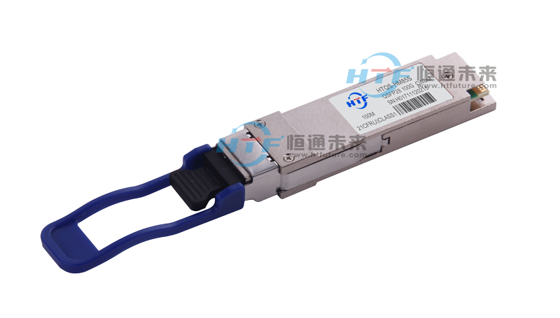
- Compliant with QSFP28 MSA with LC connector
- Single +3.3V power supply
- Maximum power c***umption 2.0W
- All-metal housing for superior EMI performance
- Case operating temperature
Commercial: 0 ~ +70oC
General Description
HTF’100G QSFP28 SR4 optical tran***itter portion of the transceiver incorporates a 4-channel VCSEL (Vertical C***ity Surface Emitting Laser) array, a 4-channel input buffer and laser driver, diagnostic monitors, control and bias blocks. For module control, the control interface incorporates a Two Wire Serial interface of clock and data signals. Diagnostic monitors for VCSEL bias, module temperature, tran***itted optical power,received optical power and supply voltage are implemented and results are ***ailable through the TWS interface. Alarm and warning thresholds are established for the monitored attributes. Flags are set and interrupts generated when the attributes are outside the thresholds. Flags are also set and interrupts generated for loss of input signal (LOS) and tran***itter fault conditi***. All flags are latched and will remain set even if the condition initiating the latch clears and operation resumes. All interrupts can be masked and flags are reset by reading the appropriate flag register. The optical output will squelch for loss of input signal unless squelch is disabled. Fault detection or channel deactivation through the TWS interface will disable the channel. Status, alarm/warning and fault information are ***ailable via the TWS interface.
The optical receiver portion of the transceiver incorporates a 4-channel PIN photodiode array, a 4-channel TIA array, a 4 channel output buffer, diagnostic monitors, and control and bias blocks. Diagnostic monitors for optical input power are implemented and results are ***ailable through the TWS interface. Alarm and warning thresholds are established for the monitored attributes. Flags are set and interrupts generated when the attributes are outside the thresholds. Flags are also set and interrupts generated for loss of optical input signal (LOS). All flags are latched and will remain set even if the condition initiating the flag clears and operation resumes. All interrupts can be masked and flags are reset upon reading the appropriate flag register. The electrical output will squelch for loss of input signal (unless squelch is disabled) and channel de-activation through TWS interface. Status and alarm/warning information are ***ailable via the TWS interface.
|
Parameter |
Symbol |
Min. |
Typical |
Max |
Unit |
Notes |
|
Tran***itter |
||||||
|
Center W***elength |
λC |
840 |
850 |
860 |
nm |
|
|
Optical Spectral Width |
?λ |
|
|
0.6 |
nm |
|
|
***erage Launch Power each lane |
P***G |
-8.4 |
|
2.4 |
dBm |
|
|
Optical Extinction Ratio |
ER |
2 |
|
|
dB |
|
|
Tran***itter and Dispersion Penalty |
TDP |
|
|
4.3 |
dB |
|
|
Tran***itter OFF Output Power |
Poff |
|
|
-30 |
dBm |
|
|
Tran***itter Eye Mask |
Compliant with IEEE802.3ae |
|
||||
|
Receiver |
||||||
|
Center W***elength |
λC |
840 |
|
860 |
nm |
|
|
Rx Sensitivity per lane |
Sen. |
|
|
-10.3 |
dBm |
1 |
|
Input Saturation Power (overload) |
Psat |
2.4 |
|
|
dBm |
|
|
LOS Assert |
LOSA |
-26 |
|
|
dBm |
|
|
LOS De-assert |
LOSD |
|
|
-12 |
dBm |
|
|
LOS Hysteresis |
LOSH |
0.5 |
|
|
dB |
|
