
| 型号 | Hp Technik | 规格 | Hp Technik |
| 品牌 | Hp Technik | 材质 | Hp Technik |
| 名称 | Hp Technik | 适用范围 | Hp Technik |
希而科贸易(上海)有限公司-德国Silkroad24 GmbH 中国***

联系人:张敏 (业务部销售经理)
TEL:13585754584 021-58375543-829
FAX:021-61179684
EMAIL:zm@
***:1784691511
MSN:zhangsir_goal@
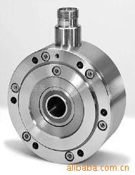
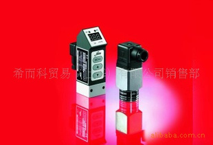
希而科优势代理德国Hp Technik GmbH阀门
产品系列:
Mode of Operation E; with adjustment screw For lubricating and hydraulic oils and many other self-lubricating, non-corrosive fluids. Maximum temperature of delivery fluid: 250 °C. Material: Casing of hydraulic cast iron (GG 25 / alternative GGG 40). Piston, valve tip, spring of hardened steel. Action: Directly controlled, spring-loaded overflow valve to maintain a set operating pressure or a set maximum pressure. |  | |
 |
2) Performance curvehere 3) No pressure stage 0, instead 1: 0.5 - 3.5 bar. Refer to chart for all other pressure stages. | ||||||||||||||||||||||||||||||||||||||||||||||||||||||||||||||||||||||||||||||||||||||||||||||||||||||||||||||||||||||||||||||||||||||||||||||||||||||||||||||||||||||||||||||||||||||||||||||||||||||||||||||||||||||||||||||||||||||||||||||||||||||||||||||||||||||||||||||||||||||||||||||||||||||||||||||||||||||||||||||||||||||||||||||||||||||||||||||||||||||||
| ||||||||||||||||||||||||||||||||||||||||||||||||||||||||||||||||||||||||||||||||||||||||||||||||||||||||||||||||||||||||||||||||||||||||||||||||||||||||||||||||||||||||||||||||||||||||||||||||||||||||||||||||||||||||||||||||||||||||||||||||||||||||||||||||||||||||||||||||||||||||||||||||||||||||||||||||||||||||||||||||||||||||||||||||||||||||||||||||||||||||
 | ||||||||||||||||||||||||||||||||||||||||||||||||||||||||||||||||||||||||||||||||||||||||||||||||||||||||||||||||||||||||||||||||||||||||||||||||||||||||||||||||||||||||||||||||||||||||||||||||||||||||||||||||||||||||||||||||||||||||||||||||||||||||||||||||||||||||||||||||||||||||||||||||||||||||||||||||||||||||||||||||||||||||||||||||||||||||||||||||||||||||
| Size Chart | ||||||||||||||||||||||||||||||||||||||||||||||||||||||||||||||||||||||||||||||||||||||||||||||||||||||||||||||||||||||||||||||||||||||||||||||||||||||||||||||||||||||||||||||||||||||||||||||||||||||||||||||||||||||||||||||||||||||||||||||||||||||||||||||||||||||||||||||||||||||||||||||||||||||||||||||||||||||||||||||||||||||||||||||||||||||||||||||||||||||||
| ||||||||||||||||||||||||||||||||||||||||||||||||||||||||||||||||||||||||||||||||||||||||||||||||||||||||||||||||||||||||||||||||||||||||||||||||||||||||||||||||||||||||||||||||||||||||||||||||||||||||||||||||||||||||||||||||||||||||||||||||||||||||||||||||||||||||||||||||||||||||||||||||||||||||||||||||||||||||||||||||||||||||||||||||||||||||||||||||||||||||


 Usage: Modulating Kit

