

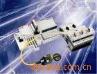
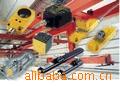
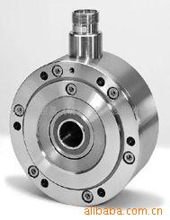
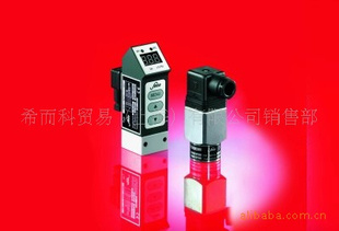
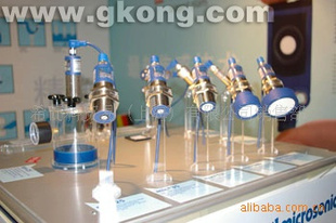
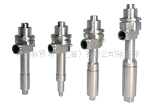
| 品牌 | 德国IPR | 型号 | 德国IPR |
| 种类 | 能耗 | 材料 | 陶瓷 |
| 材料物理性质 | 导体 | 材料晶体结构 | 单晶 |
| 制作工艺 | 集成 | 输出信号 | 数字型 |
| 防护等级 | 德国IPR | 线性度 | 德国IPR(%F.S.) |
| 迟滞 | 德国IPR(%F.S.) | 重复性 | 德国IPR(%F.S.) |
| 灵敏度 | 德国IPR | 漂移 | 德国IPR |
| 分辨率 | 德国IPR |
希而科贸易(上海)有限公司-德国Silkroad24 GmbH 中国办事处
联系人:张敏 (业务部销售经理)
TEL:13585754584 021-58375543-829
FAX:021-61179684
EMAIL:zm@
QQ:1784691511
MSN:zhangsir_goal@
希而科优势代理德国IPR - Intelligente Peripherienfür Roboter GmbH工具 模块 抓手
产品系列:
| Functional principle : | |
 | The position compensation is made possible through specially developed elastomer elements. If a position offset occurs, the workpiece to be inserted will be moved automatically by the resulting reaction forces in such a way that jamming an wedging of the parts is prevented. Depending on the chamfer present, positioning misalignments of up to 3 mm and angular misalignments of up to 2 degrees can be compensated. The compensation takes place horizontally in the x-y plane and about the x-y-z axis for angular compensation. After extension, the element returns back into the starting postition through self-centering. |
| 50 | 0,6 - 1,1 | 50 | ||
| 80 | 1,2 - 2,4 | 100 | ||
| 100 | 2,5 - 3,5 | 150 | ||
| 125 | 3,7 - 7,0 | 200 | ||
| 160 | 7,1 - 18 | 300 | ||
| 200 | 18 - 52 | 400 | ||
| 250 | 52 - 90 | 450 | ||
| 300 | 52 - 150 | 600 | ||
The length of the gripper and part (LX Value) is the determining parameter for assembly operations with close tolerance fittings and insertion operations in which minimum insertion forces are required. The LX vlaue (see table) is the maximum value which should not be exceedes for an FM type. For simple insertion or placing operations, the recommended payload is to be taken as the approximate value to determine the necessary model. It can be exceeded in case of slow travelling movements. | ||||
 Typ[mm]Empf. Handlingsgew. [kg]LX [mm]
| Model | Weight [kg] | Max. Compliance [mm] | Max. Rotation [°] | Payload [kg] | Locking Force [N bei 6 bar] |
| 0,26 | ± 3 | ± 2 | 0,6 - 1,1 | - | |
| 0,26 | ± 3 | ± 2 | 1,2 - 2,4 | - | |
| 0,3 | ± 2 | ± 2 | 1,2 - 2,4 | - | |
| 0,4 | ± 2 | ± 1 | 1,2 - 2,4 | 220 | |
| 0,45 | ± 2 | ± 1 | 1,2 - 2,4 | 220 | |
| 0,42 | ± 3 | ± 2 | 2,5 - 3,5 | - | |
| 0,46 | ± 2 | ± 2 | 2,5 - 3,5 | - | |
| 0,7 | ± 2 | ± 1 | 2,4 - 3,5 | 360 | |
| 0,82 | ± 2 | ± 1 | 2,5 - 3,5 | 360 | |
| 1,2 | ± 2 | ± 1 | 3,7 - 7,0 | 600 | |
| 1,7 | ± 2 | ± 1 | 7,1 - 18 | 500 | |
| 1,9 | ± 2 | ± 1 | 7,1 - 18 | 500 | |
| 4,0 | ± 3 | ± 1 | 18 - 52 | 1800 | |
| 4,5 | ± 3 | ± 1 | 18 - 52 | 1800 | |
| 10,1 | ± 3 | ± 1 | 52 - 90 | 2100 | |
| 10,6 | ± 3 | ± 1 | 52 - 90 | 2100 | |
| 5,8 | ± 2,5 | ± 1 | 52 - 150 | 1800 |

Functional principle:
The compensation movement is implemented through linear roller guidance based on the compound slider principle. Compensation takes place without reaction force. The fixture can be locked in a central position using a double-action pneumatic cylinder. The compensation can take place two-dimensionally in the x-y direction. |

Information:
The maximum allowable moment is the decisive parameter for the selection of the lateral alignment devices. Additional part picking or placing forces which can work as moment loads on the guides must be taken into account. If shock loads are to be expected, in case of a collision for example, a robot load limiter should be foreseen for the protection of the guides (see pages on robot load limiter systems).
| Model | KA 65KA 80KA 100KA 125KA 160KA 200KA 250KA 300||||||||
| allowable Moment[Nm] | 2 | 3 | 30 | 60 | 100 | 150 | 250 | 300 |
| Payload[kg] | 0,5 | 1,0 | 2,0 | 2-5 | 10 | 15-40 | 30-80 | 50-200 |
| Extension[mm] | ± 1,5 | ± 2 | ± 2 | ± 3 | ± 4 | ± 12 | ± 14 | ± 25 |
| Pressure Force[N] | 150 | 200 | 400 | 800 | 1000 | 1600 | 2500 | 4000 |

Functional principle:
The compensation movement is implemented through linear roller guidance based on the compound slider principle. Compensation takes place without reaction force. The fixture can be locked in a central position using a double-action pneumatic cylinder. The compensation can take place two-dimensionally in the x-y direction. |
Information:
The maximum allowable moment is the decisive parameter for the selection of the lateral alignment devices. Additional part picking or placing forces which can work as moment loads on the guides must be taken into account. If shock loads are to be expected, in case of a collision for example, a robot load limiter should be foreseen for the protection of the guides (see pages on robot load limiter systems).
| Model | KA 65KA 80KA 100KA 125KA 160KA 200KA 250KA 300||||||||
| allowable Moment[Nm] | 2 | 3 | 30 | 60 | 100 | 150 | 250 | 300 |
| Payload[kg] | 0,5 | 1,0 | 2,0 | 2-5 | 10 | 15-40 | 30-80 | 50-200 |
| Extension[mm] | ± 1,5 | ± 2 | ± 2 | ± 3 | ± 4 | ± 12 | ± 14 | ± 25 |
| Pressure Force[N] | 150 | 200 | 400 | 800 | 1000 | 1600 | 2500 | 4000 |
Functional principle:
The position compensation takes place horizontally in the pushing or pulling direction through playless ball bearings. The insertion force is determined through pressure springs and the pressure of an integrated pneumatic cylinder. The base plate is driven out to monitor an approach or insertion motion; it is inserted to monitor a removal operation (see functional sketch). The movement of the base plate is detected through an inductive sensor. In case of quick process movements, pressure can also be applied to the cylinder to block the unit. |
Information:
The Z-axis compliance wrist can be combined with a compliance wrist in the simplest. As integrated components of FM an ZN, they can be used universally for tolerance compensation of lateral and angular misalignment with simultaneous fault recognition for monitoring.
| Model ZN | 5080100125160200250300||||||||
| Spring Force[N] | 10/20 | 20/40 | 40/180 | 200/300 | 200/400 | 400/1000 | 400/1500 | 400/2000 |
| Payload[kg] | 1 | 2 | 2-3 | 5-8 | 20 | 40 | 160 | 300 |
| Insertion Path[mm] | 8 | 8 | 10 | 12 | 12 | 12 | 12 | 12 |
| Force Range Pneumatic[N] | - | 10-150 | 15-380 | 25-500 | 50-600 | 60-1700 | 70-1950 | 80-2200 |

Function
|  |
Compensation
| |
Compensation movements
| |
Arias of application:
| |
Function:
|  |
Compensation:
| |
Compensation movements:
| |
Areas of application:
| |
| Functional principle | |
 | Robot and tool adapter plates are held in position pneumatically and form a rigid unit under normal working conditions. The release forces or moments are presrcibed through the preset air pressure. In case of an overload, the adapter plates release. |
 | The robot load limiter reacts to pressure forces in the z-direction, to moments about the x and y-axes and to torsional moments about the z-axis. |
Technical Data Robot Load Limiter ULS
| Model | ULS 60ULS 80ULS 100ULS 125ULS 160ULS 200||||||
| Compensation in z-axis-direction[mm] | 11,0 | 11,9 | 13,6 | 11,9 | 14,5 | 9,5 |
| Compensation horizontal[grade] | 8 ° | 10 ° | 12 ° | 10 ° | 7 ° | 4 ° |
| Compensation torsion[grade] | 360 ° | 360 ° | 360 ° | 360 ° | 360 ° | 360 ° |
| " with Anti-rotation device[optional] | - | 90 ° | 90 ° | 40 ° | 90 ° | 90 ° |
| Axial Breakaway 1 - 6 bar[N] | 113-680 | 181-1085 | 246-1477 | 453-2720 | 785-4710 | 1327-7960 |
| Moment Breakaway 1 - 6 bar[Nm] | 2 - 13 | 4 - 26 | 7 - 41 | 17 - 103 | 39 - 236 | 86 - 517 |
| Repeatability[mm] | ± 0,02 | ± 0,02 | ± 0,03 | ± 0,03 | ± 0,05 | ± 0,1 |
| Weight[kg] | 0,36 | 0,42 | 0,75 | 1,5 | 6,7 | 9,8 |


Technical Data Robot Load Limiter with internal cable routing (ULD)
| Model | ULD 60ULD 80ULD 100ULD 125ULD 160ULD 200ULD 250ULD 300||||||||
| Compensation in z-axis-direction[mm] | 11,1 | 12,1 | 12,0 | 12,1 | 15,0 | 10,4 | 15,0 | 23,0 |
| Compensation horizontal[grade] | 9 ° | 11 ° | 9 ° | 11 ° | 5 ° | 4 ° | 5 ° | 5 ° |
| Compensation torsion[grade] | 40 ° | 40 ° | 40 ° | 40 ° | 40 ° | 40 ° | 40 ° | 40 ° |
| Axial Breakaway 1-6 bar[N] | 135-700 | 210-1100 | 300-1500 | 510-2755 | 830-4720 | 1380-6710 | 1509-9024 | 1834-11389 |
| Moment Breakaway 1-6 bar[Nm] | 3-15 | 5-28 | 8-45 | 18-106 | 43-241 | 91-382 | 108-544 | 119-714 |
| Repeatability[mm] | ± 0,02 | ± 0,02 | ± 0,03 | ± 0,03 | ± 0,05 | ± 0,1 | ± 0,1 | ± 0,1 |
| Weight[kg] | 0,39 | 0,46 | 0,83 | 1,65 | 3,58 | 5,78 | 12,4 | 17,5 |


Two - Finger Parallel Gripper
with roller bearing
|
|
| Functional principle: | |
The parallel movement of the finger is accomplished by a jaws and pinion drive. As a result of the pressure of two opposing pistions the jaws move in a synchronised way towards each other. | |
OPTIONS:
Sensors
Option C "gripper closed", Option O "gripper open". For the position of the inductive sensors please refer to the technical data of the gripper concerned.
Gripping Force Failsafe valve
A safety device for the gripping force by means of a spring is available as an option. The chuck stroke of the gripper is reduced by 50 %. The safety device can be applied for both inside and outside gripping.
Inside gripping = FS - 1
Outside gripping = FS - A
Pressure Medium
P = compressed air
H = hydraulic oil
| Model | RPG 80-PRPG 120-PRPG 120-H|||
| Max. air pressure[bar] | 8 | 8 | 100 |
| Gripping force at 6 bar[N] | 1000 | 1000 | - |
| Gripping force at 60 bar[N] | - | - | 2000 |
| Gripping force at 100 bar[N] | - | - | 3000 |
| Weight[kg] | 8,5 | 9,0 | 10,5 |
| Stroke[mm] | 80 | 120 | 120 |
| Displacement[cm³] | 2x128 | 2x192 | 2x23,56 |

Electric Grippers
The electronic grippers in the EGS series are designed to cope with very difficult applications where a high degree of flexibility is needed.
All systems are of a strong mechanical construction which allows of a maintenance-free operation. To ensure that our system can be used to optimal effect in a wide range of different situations, we have designed 3 basic models for you to choose from.
Following basic versions are available:
EGS-EP Compactwith a combined electro-pneumatic drive
- Great flexibility, because the opening width can be adjusted to any size
you wish via the electric servo drive. - Large gripping power and short travelling times via the pneumatic drive
- Extra measuring capabilities, such as the monitoring of parts dimensions
EGS-E Compactwith a regulated electric servo drive
- Safe handling of sensitive parts
- Measuring and monitoring functions
- Can be used in clean rooms
EGS-ELTLightwith a simple electric drive
- In areas where there is no compressed air
- Especially suited for clean rooms
| Functional principle: | |
| |

| Model EGS- | 250-EP250-E/-ELT375/1-EP375/1-E/-ELT375/2-EP|||||
| Gripping force electrical[N] | - | 155 | - | 180 | - |
| Gripping force pneumaticalat 6 bar [N] | 155 | - | 330 | - | 330 |
| Duration(for 19mm strokechange in s) | 0,1 | 0,25 | 0,15 | 0,25 | 0,15 |
| Stroke[mm] | 19 | 19 | 25,4 | 25,4 | 50,8 |
| Repeatability[mm] | <0,1 | <0,1 | <0,1 | <0,1 | <0,1 |
| Electrical performance of servo[W] | 10 | 25 | 25 | 30 | 25 |
| Weight[kg] | 1,23 | 1,28 | 1,56 | 1,59 | 1,56 |
| Max. air pressure[bar] | 8 | - | 8 | - | 8 |
| Displacement[cm³] | 3,75 | - | 9,78 | - | 19,56 |
| Cylinder bore[mm] | 16,0 | - | 22,22 | - | 22,22 |
| Recommended payload[kg] | 0,5 | 0,5 | 1,5 | 0,75 | 1,5 |

| Model EGS- | 375/2-E/-ELT-500/1-EP500/1-E/-ELT500/2-EP500/2-E/-ELT|||||
| Gripping force electrical[N] | 180 | - | 330 | - | 330 |
| Gripping force pneumaticalat 6 bar [N] | - | 690 | - | 690 | - |
| Duration(for 19mm strokechange in s) | 0,25 | 0,15 | 0,25 | 0,15 | 0,25 |
| Stroke[mm] | 50,8 | 38,1 | 38,1 | 63,5 | 63,5 |
| Repeatability[mm] | <0,1 | <0,1 | <0,1 | <0,1 | <0,1 |
| Electrical performance of servo[W] | 30 | 40 | 75 | 40 | 75 |
| Weight[kg] | 1,59 | 3,2 | 3,4 | 3,7 | 3,9 |
| Max. air pressure[bar] | - | 8 | - | 8 | - |
| Displacement[cm³] | - | 29,5 | - | 49,1 | - |
| Cylinder bore[mm] | - | 32,0 | - | 32,0 | - |
| Recommended payload[kg] | 0,75 | 4 | 2 | 4 | 2 |