
TCXO温补晶振10MHz CFPT-9003 EX 1 B
|
TCXO |
|
ISSUE 7; 24 MARCH 2004 |
|
Recommended for New Designs |
|
Delivery Opti*** |
|
I |
|
10MHz CFPT-9003 EX 1 B |
|
Frequency Stability |
|
I |
|
I |
|
I |
|
Temperature: see table |
|
Typical Supply Voltage Variation &plu***n;10% < &plu***n;0.2 ppm* |
|
Typical Load Coefficient 15pF &plu***n;5pF < &plu***n;0.2 ppm* |
|
*Dependant on frequency and output type |
|
Please contact our sales office for current leadtimes |
|
Description |
|
I |
|
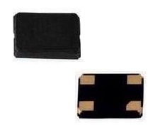
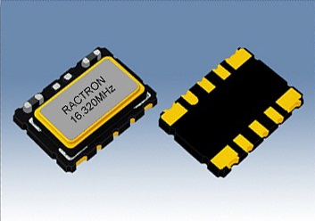
A series of surface mountable 7.0 × 5.0mm TCXOs for medium to high volume applicati*** where ***all size and high performance are pre-requisites. This oscillator uses C-MAC’s latest custom ASIC "Pluto", a single chip oscillator and analogue compensation circuit, capable of sub 1 ppm performance over an extended tempera- ture range. Its ability to function down to a supply volt- age of 2.4V and low power c***umption make it partic- ularly suitable for mobile applicati*** |
|
Frequency Adjustment |
|
I |
|
Three opti*** with external Control Voltage applied to pad 10: |
|
A - Ageing adjustment: > &plu***n;5ppm, frequency < 20MHz (Standard Option) |
|
> &plu***n;7ppm, frequency > 20MHz |
|
B - No frequency adjustment initial calibration @ 25°C < &plu***n;0.5 ppm |
|
C - High Pulling &plu***n;10ppm to &plu***n;50ppm can be ***ailable depending on frequency and stability opti***. Please c***ult our sales office |
|
Standard Frequencies |
|
I |
|
10MHz |
|
I |
|
Linearity |
|
Slope |
|
Input resistance |
|
Modulation bandwidth |
|
Standard control voltage ranges: |
|
Without reference voltage |
|
Without reference voltage |
|
With reference voltage |
|
< 1% |
|
Positive |
|
> 100k? |
|
> 2kHz |
|
Output W***eform |
|
I |
|
I |
|
I |
|
I |
|
I |
|
I |
|
Square HCMOS 15pF load |
|
Square ACMOS 50pF max. load (***ailable on request, contact sales office) |
|
Sinew***e 10k? // 10pF AC-coupled, |
|
Clipped sinew***e 10k? // 10pF AC-coupled, |
|
SURFACE MOUNT TCXOs |
|
- Vs=5.0V 2.5V&plu***n;1V |
|
- Vs=3.3V 1.65V&plu***n;1V |
|
- Vc=0V to Vref |
|
Supply Voltage |
|
I |
|
Operating range 2.4 to 6.0V, see table |
|
Reference Voltage, Vref |
|
I |
|
Current C***umption |
|
I |
|
HCMOS Typically ≈ 1+Frequency(MHz)*Supply(V)*{Load(pF)+15}*10-3 mA E. g. 20MHz, 5V, 15pF ≈ 4mA |
|
Sinew***e Typically < 8mA |
|
Clipped Sinew***e Typically ≈ 1+Frequency(MHz)*1.2*{Load(pF)+30}*10-3 mA |
|
Optional reference voltage output on pad 1, suitable for potentiometer supply or DAC reference. |
|
1. No output (Standard option) |
|
2. 2.2V, for Min. Vs>2.4V |
|
3. 2.7V, for Min. Vs>3.0V |
|
4. 4.2V, for Min. Vs>4.5V |
|
Maximum load current (mA) = Vref /10 |
|
I |
|
I |
|
Package Outline |
|
I |
|
7.0 x 5.0 x 2.0mm ***D (Surface mount device) ceramic carrier |
|
For manual frequency adjustment connect an external 50K? potentiometer between pad 1 (Reference Voltage) and pad 4 (Ground) with wiper connected to pad 10 (Voltage Control). Please specify reference voltage as part of the ordering code |
|
Tri-state |
|
I |
|
Ageing |
|
I |
|
I |
|
I |
|
I |
|
I |
|
&plu***n;1ppm maximum in first year, frequency < 20MHz |
|
&plu***n;2ppm maximum in first year, frequency > 20MHz |
|
Pad 8 open circuit or >0.6Vs output enabled |
|
< 0.2Vs Tri-state |
|
When Tri-stated, the output stage is disabled for all out- put opti***, but the oscillator and compensation circuit are still active (Current c***umption <1mA) |
|
I |
|
&plu***n;3ppm maximum for 10 years, frequency < 20MHz |
|
&plu***n;5ppm maximum for 10 years, frequency > 20MHz |
|
&plu***n;1ppm maximum after reflow |
TCXO温补晶振10MHz CFPT-9003 EX 1 B