

AC Current Probes Datasheet
CT1 • CT2 • CT6电流探头
Features & Benefits
- High Bandwidth
- Ultra-low Inductance
- Very ***all Form Factor
- Characterize Current W***eforms up to <200 ps Rise Times
- Very Low Loading of Circuit Under Test
- Fits Into Dense, Closely-spaced Circuit Designs
Applicati***
- Data Storage Read Channel Design
- Silicon Characterization
- High-frequency Analog Design
- ESD Testing
- Signal Injection
- Differential Current Measurements
- Single-shot Low Rep-rate Pulse Measurements
- Propagation Delay Measurement
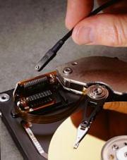
CT6 Current Probe
The CT6 is the newest addition to the Tektronix portfolio of high-frequency current probes. It is designed to meet the needs of high-speed circuit design and test applicati*** which require ultra-high bandwidth, low inductance, and extremely ***all form factor. The CT6 provides up to 2 GHz bandwidth when used with high-bandwidth oscilloscopes such as the Tektronix TDS694C, TDS794D, and TDS7000 Series oscilloscopes or with other compatible 50 Ω input measuring instruments. Low inductance (<3 nH) assures that the loading effect of the CT6 on the circuit-under-test will be negligible, which is especially important for today's low-amplitude, high-speed circuit designs such as disk drive read/write preamplifiers. The probe is a closed-circuit design which will accept uninsulated wire sized up to 20 gauge. This product is exempt from CE mark by virtue of its 30 V voltage limit.
CT1/CT2 Current Probes
The CT1 and CT2 Current Probes are designed for permanent or semi-permanent in-circuit installation. Each probe c***ists of a current transformer and an interconnecting cable. The current transformers h***e a ***all hole through which a current carrying conductor is passed during circuit assembly.
The P6041 Probe Cable provides the connection between the CT1 and CT2 Current Transformers and a BNC oscilloscope input. A 50 Ω termination is required to terminate the cable when connected to a high-impedance (1 MΩ) oscilloscope input. One probe cable can be used to monitor several current transformers that h***e been wired into a circuit.
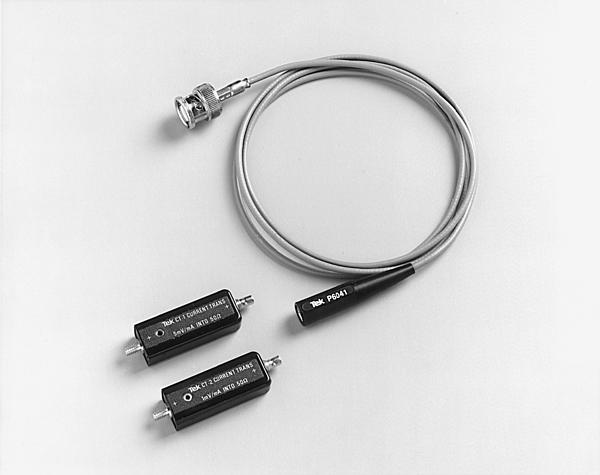
CT1/CT2. Current Probes with P6041 BNC Probe Cable.
Miniature C***truction
The CT1 and CT2 detachable cable design enables one or more probes to be located on circuit boa*** or in other limited space areas.
The CT6 offers the ***allest form factor ***ailable, for measurement on ever-shrinking circuit boa*** and components. It is designed for temporary installation and does not incorporate removable cables, as the CT1 and CT2 do.
Extendible Probe Length
Specified rise time and bandwidth are obtained when using the probe cables provided: The P6041 cable used with the CT1 and CT2 is 42 inches nominal. If additional length is required, the cables can be extended by using high-quality 50 Ω cable and suitable interface connectors. (Also see Special Probe Cables, Optional Accessories.) Long cables may degrade high-frequency resp***e.
High Sensitivity
The CT1 and CT6 provide an output of 5 mV for each milliamp of input current when terminated in 50 Ω. The CT2 provides 1 mV per milliamp when terminated in 50 Ω.
Typical Systems
The CT1, CT2, and CT6 high-frequency current transformers are dynamic (i.e., non-DC) current measuring devices. They are typically used in conjunction with compatible high-bandwidth oscilloscopes and other instruments to observe and/or record high-frequency current w***eforms. The CT1, CT2, and CT6 normally operate directly into 50 Ω scopes and other measuring device inputs.
The CT1 or CT2 can be used with 1 MΩ input systems; use the P6041 probe cable and terminate the output with a 50 Ω feed-through termination (see Optional Accessories).
In all cases, the CT1, CT2, and CT6 must work into 50 Ωs to obtain specified performance and sensitivity.
Typical Measurement Applicati***
Differential Current Measurements
Most true-differential voltage amplifiers h***e a maximum bandwidth of about 100 MHz. The CT1 or CT6 can make differential current measurements to 1 GHz and 2 GHz, respectively, by passing two wires carrying opposing currents through the same core. The displayed result is the difference current. The CT2 can perform the same function to 200 MHz.
In all cases, Derating with Frequency and Amp-second Product (Current-time Product) guidelines should not be exceeded. (See Characteristics.)
Single-shot and Low Rep-rate Pulse Measurements
These common measurements are easy to make with the CT1, CT2, or CT6 provided that your signal fits within the Max Pulse Current and Amp-second Product (Current-time Product) guidelines for the specific current probe characteristics.
For example, the CT2 is rated at 36 A peak, with an Amp-second Product of 50 × 10-6 seconds (50 Amp-microseconds), therefore the CT2 can safely handle a 36 A peak pulse with a maximum width of 1.39 microseconds or lower amplitude pulses for longer pulse widths. The CT1, CT2, and CT6 all h***e low-frequency roll-off characteristics. Low-frequency "droop" will exhibit itself when the pulse width approaches the L/R time c***tant of the specific transformer.
Propagation Delay Measurements
Two CT1 or CT2 Current Transformers with matching probe cables can be used to measure propagation delay (transit time) between the input and output currents of high-frequency devices. The probe outputs are connected to the inputs of dual-channel real-time or sampling scopes.
Verification of any Probe/Cable/Scope System mi***atch can be obtained by passing the same signal current through both probes and observing total system delay difference, if any.
Characteristics

CT1 Typical Frequency Resp***e.

CT2 Typical Frequency Resp***e.

CT6 Typical Frequency Resp***e.
CT1, CT2, and CT6 Characteristics
|
Characteristic |
CT1 |
CT2 |
CT6 |
|---|---|---|---|
|
Bandwidth (typical) |
25 kHz to 1 GHz |
1.2 kHz to 200 MHz |
250 kHz to 2 GHz |
|
Rise Time |
350 ps |
500 ps |
200 ps |
|
Sensitivity (into 50 Ω) |
5 mV/mA |
1 mV/mA |
5 mV/mA |
|
Accuracy |
&plu***n;3% |
&plu***n;3% |
&plu***n;3% |
|
Magnetizing Inductance |
6 μH |
7 μH |
1 μH |
|
Leakage Inductance |
2.4 nH |
1 nH |
1.5 nH |
|
Insertion Impedance: |
|||
|
at 10 MHz |
<1 Ω |
0.1 Ω |
1.1 Ω |
|
at 100 MHz |
2 Ω |
0.5 Ω |
1.3 Ω |
|
at 1 GHz |
|
|
11.9 Ω |
|
Max. Bare Wire Size |
#14 wire |
#16 wire |
#20 wire |
|
1.78 mm (0.070 in.) |
1.32 mm (0.052 in.) |
0.8 mm (0.032 in.) |
|
|
Max. Bare Wire Voltage: |
|||
|
RMS |
175 VRMS CAT I |
175 VRMS CAT I |
30 VRMSCAT I |
|
Peak |
1000 V*1 |
1000 V*1 |
30 V |
|
DC |
175 V |
175 V |
30 V |
|
Max. Peak Pulse Current |
12 A |
36 A |
6 A |
|
Max. Continuous Current (RMS) |
450 mA |
2.5 A |
120 mA |
|
Amp-second Product |
1 × 10⁻⁶ A*Sec |
50 × 10-6 A*Sec |
0.25 × 10⁻⁶A*Sec |
|
L/R Time C***tant (droop) |
>6.35 μs |
>160 μs |
0.4 μs |
|
Propagation Delay |
5.4 ns |
6.1 ns |
5.2 ns |
|
Safety |
UL3111-2-032, CSA1010.2.032, EN61010-2-032, IEC61010-2-032 |
UL3111-2-032, CSA1010.2.032, EN61010-2-032, IEC61010-2-032 |
NA |
*1 (<3.25% Duty Factor).