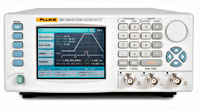
| 397 高性能双通道任意波形发生器 |
 |
|
| Waveforms |
| Waveforms |
| |
Standard waveforms: sine, square, triangle, ramp, sinc, pulse, noise, Gaussian as well as dc |
|
| Sine |
| Range |
0.1 mHz to 50 MHz |
| Resolution |
7 digits or 0.1 mHz |
| Accuracy |
< 1 ppm for 1 year |
| Temp. coefficient |
< 1 ppm/°C |
| Harmonic distortion and non related spurious below 10 MHz |
< 0.1 % THD to 100 kHz (2000 waveform points) |
| |
< –55 dBc to 1 MHz |
| |
< –40 dBc to 5 MHz |
| |
< –35 dBc to 10 MHz |
| |
< –22 dBc to 50 MHz |
|
| Square |
| Range |
0.1 mHz to 50 MHz |
| Resolution |
0.1 mHz or 7 digits |
| Rise and fall times |
< 10 ns |
|
| Triangle |
| Range |
0.1 mHz to 12.5 MHz |
| Resolution |
0.1 mHz or 7 digits |
| Accuracy |
1 ppm for 1 year |
| Linearity error |
< 0.1 % to 100 kHz |
|
| Pulse |
| Range |
0.1 mHz to 12.5 MHz |
| Delay |
0 % to 99.9 % of period |
| Rise and fall times |
0 % to 99.9 % of period |
| High time |
0 % to 99.9 % of period |
| Resolution |
0.10% |
|
| Arbitrary Waveforms |
| Stored waveforms |
397: Up to 4096 each channel |
| Waveform length |
16 to 4 M points |
| Vertical resolution |
14 bits |
| Sample clock range |
100 mHz to 125 MHz |
| Waveform sequencing |
Up to 4096 segments may be linked. Minimum segment duration 1 µs. Segments can be looped up to 1,000,000 times |
|
| Amplitude |
| Output impedance |
50 Ω |
| Amplitude Range |
10 mVpp to 10 Vpp (20 mVpp to 20 Vpp into open circuit) |
| Accuracy |
< 1 % ± 25 mV between 1 V to 10 Vpp into 50 Ω |
| Flatness |
± 5 % to 10 MHz; ± 20 % to 50 MHz |
| DC offset |
± 4.5 V into 50 Ω. DC offset plus signal peak limited to ± 10 V. DC offset attenuated with amplitude range |
|
| Output Filters |
| |
50 MHz Elliptic and 2 MHz Elliptical |
|
| Modulation Modes |
| Triggered burst |
Each active edge of the trigger signal will produce one burst of the carrier waveform, waveforms starts from point n and completes at point n-1 |
| Gated |
The selected waveform is output continuously at the programmed frequency while the selected gate signal is true |
| Waveforms |
All standard and arbitrary |
| Carrier frequency |
125 Msample/s for ARB and Sequence. 2.5 MHz or the maximum of selected waveform |
| No. of cycles |
1 to 1,000,000 |
| Trigger source |
Manual trigger key, adjacent channel or internal trigger generator or external trigger input or remote trigger command |
| Trigger rate |
Internal trigger generator: 0.1 Hz to 2 MHz; External signal: dc to 2 MHz |
| Start/stop phase |
± 360 ° , settable to 0.1 ° subject to waveform frequency and type |
| Frequency sweep |
Manual, continuous, triggered; linear or logarithmic sweep; up or down. Variable sweep marker. |
| Sweep range |
1 mHz to 125 MHz |
| Sweep time |
1 ms to 999 s |
| Sweep trigger source |
External trigger input or remote trigger command |
| Tone switching |
FSK tone switching for all waveforms |
| External AM |
Via rear panel BNC input, dc-500 kHz for all standard and arbitrary waveforms |
|
| Outputs and Inputs |
| Main outputs |
|
| Sync outputs |
| |
Front panel BNC connector generates sync pulse synchronous with output waveform. In FM and sweep modes this output is synchronous with sample clock frequencies |
|
| Ext. trigger |
| |
DC to 2 MHz. Threshold nominally TTL level; maximum input 5 V. Selectable as positive rising edge or negative falling edge. Minimum pulse width 20 ns for trigger and gated modes |
|
| AM input |
| |
0 V to +5 V (5 Vpp) produce 100 % modulation |
|
| Ref clock in |
| |
Input for an external 10 MHz reference clock. Threshold nominally TTL level. |
|
| SCLK output, SCLK input and DSUB connector |
| |
Connect instruments to achieve synchronization. DSUB 9- pin connector and cable supplied. |
|
| Inter-Channel Operation |
| Inter-channel modulation |
| |
The waveform from any channel may be used to amplitude modulate (AM) the adjacent instrument/channel. Alternatively, any number of channels may be modulated (AM) with the signal at the modulation input socket. |
|
| Carrier frequency |
| |
Entire range for selected waveform |
|
| Carrier waveforms |
| |
All standard and arbitrary waveforms |
|
| Modulation freq. |
|
| Modulation depth |
|
| Inter-channel synchronization |
| 397:00:00 |
Both channels are tightly synchronized in phase and waveform start. Channel 2 has sample clock divider for arbitrary and sequenced waveforms. |
|
| Phase resolution |
| 397:00:00 |
1 sample clock period of channel 2 |
|
| Skew error |
|
| Inter-instrument synchronization |
| |
Two or more instrument may be slaved to one master instrument. Each Slave can have a unique phase resolution relative to the Master. |
|
| Phase error |
|
| Skew error |
| |
+/-20ns Typically with 20c"m coax cable |
|
| General Specifications |
| Waveform Software |
| |
ArbExplorer Software for Windows is supplied with each instrument. This provides full waveform creation, editing and management including an equation editor, clipboard import/export and freehand drawing. |
|
| Interface types |
| 397:00:00 |
GPIB, USB and Ethernet |
|
| Remote control |
| |
Full remote control facilities are available through the interfaces |
|
| RS-232 |
| |
Variable Baud rate, 115 k Baud. 9-pin D-connector |
|
| GPIB |
| |
Conforms with IEEE-488.1 and IEEE-488.2 |
|
| Ethernet |
| 397:00:00 |
Twisted pair 10/100Base-T, auto negotiation |
|
| USB |
| 397:00:00 |
Type A receptacle, version 2.0 |
|
| Display |
| 397:00:00 |
3.5 in color LCD reflective, 320 x 240 pixels, back-lit |
|
| Size |
| |
88 x 415 x 212 mm (H x D x W) |
|
| Weight |
|
| Power |
| |
85 V to 265 V, 48 - 63 Hz, 60W |
|
| Operating temperature range |
|
| Operating humidity (non condensing) |
| |
11 °C to 30 °C 85 % RH; |
| |
31 °C to 40 °C 75 % RH; |
| |
41 °C to 50 °C 45 % RH |
|
| Storage range |
|
| Environmental |
| |
Operating altitude: 10,000 feet |
| |
Storage: 15,000 feet |
| |
Pollution degree 2 |
|
| Safety |
|
| EMC |
| |
Complies with EN61326, CE marked |
|
|
|
|